Posted by Roth on | Comments Off on What Is NPSH and Why Does It Cause Cavitation?
If you’ve ever heard a pump that sounds like it’s pumping gravel, you’ve heard cavitation. It’s one of the most common causes of pump damage, and almost always it comes down to one number: NPSH. Here’s what NPSH means, why a shortage of it destroys pumps, and how to make sure your pump has enough.
What Does NPSH Stand For?
NPSH stands for Net Positive Suction Head. In plain English, it’s the amount of pressure a liquid has at the pump inlet above the pressure at which it would boil. It’s expressed in feet (or meters) of the liquid being pumped.
Every liquid has a vapor pressure: the pressure at which it turns to vapor at a given temperature. Water at 60°F has a vapor pressure of only about 0.26 psia, so it stays liquid easily. Water at 212°F has a vapor pressure of 14.7 psia, the same as the atmosphere, so in an open tank it’s right at the boiling point. Liquefied gases like propane and ammonia are stored at their vapor pressure all the time.
NPSH is simply the cushion between the pressure at the pump suction and the liquid’s vapor pressure. The bigger the cushion, the less likely the liquid is to boil inside the pump.
NPSHa vs. NPSHr
There are two NPSH numbers, and comparing them is the whole game:
NPSHa (NPSH available) is what your system provides. It depends on your tank, piping, liquid temperature and elevation. You calculate it.
NPSHr (NPSH required) is what the pump needs to avoid cavitating. It depends on the pump’s design, speed and flow rate. The pump manufacturer publishes it on the pump curve.
The rule: NPSHa must be greater than NPSHr, with a safety margin. Published NPSHr is typically the point where the pump has already lost about 3% of its head to cavitation, so running with NPSHa just equal to NPSHr means the pump is already cavitating.
What Is Cavitation?
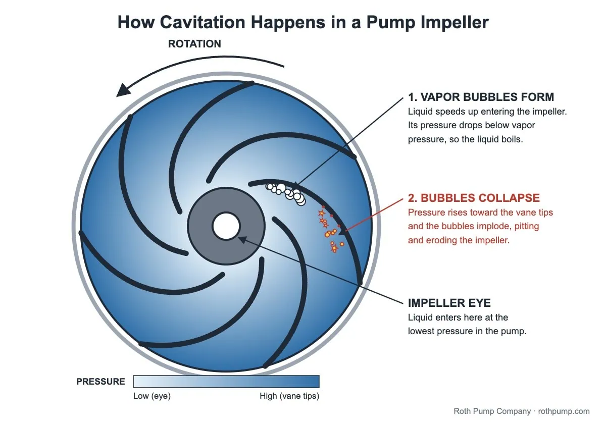
As liquid enters a pump, it speeds up at the inlet of the impeller, and its pressure drops. If that pressure falls below the liquid’s vapor pressure, the liquid boils right there inside the pump and forms vapor bubbles, even if the liquid is cold.
Those bubbles are then carried into higher-pressure areas of the pump, where they collapse violently. Each collapse fires a tiny, high-velocity jet of liquid against the metal. Millions of them, over and over, tear away at the impeller and casing. That’s cavitation.
Signs your pump is cavitating
A noise like gravel, marbles or popcorn rattling through the pump
Excess vibration
Lower flow or discharge pressure than the pump curve predicts, or pressure that fluctuates
Pitted, sponge-like erosion on the impeller vanes, especially near the inlet
Repeated mechanical seal and bearing failures
Cavitation doesn’t just wear out impellers. The vibration it causes shortens the life of seals and bearings, and in severe cases the pump can lose prime entirely.
Water at 60°F (vapor pressure 0.26 psia) is pumped from an open tank at sea level. The water level is 5 ft above the pump and suction friction loss is 2 ft.
NPSHa = 2.31 × (14.7 − 0.26) ÷ 1.0 + 5 − 2 = about 36 ft
That’s plenty for almost any pump. Cold water rarely has NPSH problems.
Example 2: Condensate at 212°F
Now the same tank holds condensate at 212°F in a vented receiver. The vapor pressure is 14.7 psia, exactly equal to the pressure on the surface, so the pressure term is zero. With 3 ft of liquid above the pump and 1 ft of friction loss:
NPSHa = 0 + 3 − 1 = 2 ft
Many standard centrifugal pumps need 6 to 10 ft or more of NPSH. Put one on this receiver and it will cavitate. Hot water, condensate and boiler feed water are where most NPSH problems happen, along with liquefied gases and volatile solvents stored at their boiling point.
Don’t forget altitude
Atmospheric pressure drops as elevation rises. In Denver it’s about 12.2 psia instead of 14.7, which costs roughly 6 ft of NPSHa on an open water tank.
How to Prevent Cavitation
You can fix an NPSH problem from either side: raise NPSHa or lower NPSHr.
Increase NPSH available
Raise the supply tank or lower the pump to add static head.
Reduce suction friction with a larger-diameter, shorter suction line, fewer elbows and fittings, and clean strainers.
Never throttle the suction valve to control flow. Throttle on the discharge side instead.
Lower the liquid temperature, if the process allows, to reduce vapor pressure.
Pressurize the supply vessel above the liquid’s vapor pressure.
Choose a pump with lower NPSH required
Often the tank height and liquid temperature are fixed, and the practical answer is a pump designed to run on very little NPSH. Roth Pump has designed and built pumps since 1932. Roth regenerative turbine pumps with inducer stages require as little as 1 ft (0.3 m) of NPSH, so they can pump liquids at or near their boiling point without cavitating:
Posted by Roth on | Comments Off on Sealless Magnetic Drive Pumps for Low-NPSH and Near-Boiling Liquids
Liquefied gases and volatile chemicals are some of the hardest liquids to pump. They arrive at the pump at or near their boiling point, they often can’t be allowed to leak, and many applications need high pressure at low flow. A sealless magnetic drive pump solves the leak problem. But on near-boiling liquids, a mag drive brings its own risks. Here’s what to watch for, and how Roth’s one-foot NPSHr regenerative turbine mag drive pumps are designed around them.
Why Choose a Sealless Pump for Volatile Liquids?
A conventional pump seals its rotating shaft with a mechanical seal, and every mechanical seal eventually leaks or fails. For water that’s a maintenance item. For anhydrous ammonia, hydrofluoric acid, vinyl chloride or propane, a seal leak is a safety, environmental and emissions problem.
A magnetic drive pump has no shaft seal at all. The motor turns an outer ring of magnets, which drives an inner magnet rotor through a sealed containment shell (the “can”). The liquid stays completely enclosed, with only a static O-ring or gasket between the containment shell and the pump casing. That makes mag drive pumps the natural choice for:
Liquefied gases such as ammonia, propane, butane and refrigerants
Hazardous and toxic liquids
Caustic and corrosive liquids
Liquids that react when released to the atmosphere
The Challenge: Mag Drive Pumps and Near-Boiling Liquids
Removing the seal doesn’t remove the physics. Three things make volatile liquids hard on a magnetic drive pump:
Little or no NPSH available. A liquid stored at its boiling point, like propane in a pressurized tank or ammonia in a refrigerated vessel, has a vapor pressure equal to the pressure above it. The only NPSH available comes from the few feet of liquid above the pump. If the pump needs more NPSH than that, the liquid flashes to vapor and the pump cavitates. (See our chemical boiling point and specific gravity chart and NPSH Calculator.)
Heat inside the can. Eddy currents in a metal containment shell and friction in the internal bearings add heat to the liquid circulating inside the pump. With a liquid already near its boiling point, a small temperature rise can turn it to vapor.
Product-lubricated bearings. A mag drive’s internal bearings are lubricated by the pumped liquid. If that liquid flashes to vapor, the bearings run dry and can fail quickly. Cavitation-induced vibration adds to the damage.
Low flow makes all three worse. Many liquefied gas and chemical transfer applications need only a few gallons per minute at high pressure, which is exactly where conventional centrifugal pumps run least efficiently and add the most heat.
How Roth Mag Drive Pumps Handle Near-Boiling Liquids
Roth sealless pumps combine a magnetic drive with Roth’s regenerative turbine design. The result is built specifically for continuous high-pressure pumping of liquefied gases.
1 ft (0.3 m) NPSHr across the full range
Every Roth mag drive model requires only 1 ft (0.3 m) of NPSH. That’s often the difference between a pump that works on a liquid at its boiling point and one that cavitates.
A non-cavitating regenerative turbine impeller
Roth’s floating, self-centering regenerative turbine impeller (U.S. Patent No. 5,137,418) develops high pressure at low flow: up to 1,500 ft (457 m) of head at flows up to 180 GPM (40 m³/hr). The non-cavitating design keeps destructive vibration away from the bearings.
A cooling flush that keeps the liquid in liquid phase
Liquid at discharge pressure is routed through the pump’s inboard cover to the inside of the containment can. It flows around the inside of the can, then through the alpha-grade sintered silicon carbide radial and thrust bearings, before returning to a lower-pressure point in the pump and rejoining the pump output. This flush circuit:
Removes heat generated by eddy currents, controlling the liquid’s vapor pressure
Forces liquid through the bearings, which have lubrication grooves to keep the surfaces wetted
Keeps the bearing flush in liquid phase, because the regenerative turbine’s high discharge pressure provides a wide margin above vapor pressure
Low-loss containment shells
The standard Hastelloy C containment shell reduces eddy current losses, which means less heat added to the liquid, lower power consumption and higher torque capability. It’s rated for pressures up to 362 psi (24.9 bar). For applications above 25 HP (18.6 kW), a high-efficiency segmented 316 stainless steel containment shell is rated to 660 psi (45.5 bar). The primary containment shell is self-venting back to the supply vessel.
Materials for corrosive service
Pump cases are available in ductile iron, 316 stainless steel and Hastelloy C. Internal bearings and shaft sleeve are alpha-grade silicon carbide, with duplex stainless steel inner rotor and bearing housing.
Proven in Real Applications
Roth mag drive pumps are in service on a wide range of volatile and hazardous liquids. A few examples from our application list:
Liquid
Flow (GPM)
TDH (ft)
Temperature (°F)
Anhydrous ammonia
22
700
11
Butane and propane
10–12
763
60
Anhydrous hydrofluoric acid (HF)
21
616
70
Vinyl chloride monomer (VCM)
9
579
Ambient
Refrigerant (Genetron AZ-50)
50
185
−65
Vinylidene fluoride
30
1,385
16
Methyl chloride
4
215
14–104
Other applications include aqueous ammonia, F152a, propylene oxide, trimethylamine, caustic, isoprene and sour water.
Installation Tips for Mag Drive Pumps on Volatile Liquids
Good piping is just as important as the pump. Roth recommends:
Slope the suction line uphill toward the supply vessel, with no reverse loops, so any vapor can rise back to the vessel instead of collecting at the pump.
Route the flush and vent lines back to the supply vessel, also sloped uphill with no reverse loops or dead legs.
Vent the pump before start-up. Open the vent valve for initial start-up and close it afterward (an optional solenoid valve with time delay can automate this).
Protect against over-pressurization with a suitable discharge bypass valve, returned to the supply vessel rather than directly over the suction outlet.
Consider a flow switch on the flush line to confirm cooling flow.
If you’re pumping a liquefied gas, a hazardous chemical, or any liquid close to its boiling point, Roth’s 1 ft NPSH sealless magnetic drive pumps are built for the job. Send us your liquid, temperature, suction pressure, flow and required discharge pressure, and we’ll recommend a model. Contact Roth Pump, call 1-888-444-ROTH, or find your local Roth representative.
Posted by Roth on | Comments Off on 10 Common Reasons Industrial Pumps Fail
Top 10 Reasons Industrial Pumps Fail
Industrial pumps are critical assets in manufacturing, chemical processing, and water treatment operations.
Unexpected pump failures can halt production, damage downstream equipment, and incur substantial costs in downtime and repairs. While pumps are engineered for reliability, premature failure often arises from operational, installation, or design deficiencies. Understanding the root causes of pump failure is essential for optimizing performance, extending service life, and maintaining system reliability.
1. Improper Installation
Misalignment between the pump and driver, inadequate foundation rigidity, or suboptimal piping layouts can induce mechanical vibrations, shaft deflection, and uneven loading. These conditions accelerate wear on bearings, mechanical seals, and impellers, and can lead to early catastrophic failures. Precision alignment and vibration monitoring during commissioning are critical to preventing these issues.
2. Cavitation
Cavitation occurs when local pressure at the pump suction falls below the liquid’s vapor pressure, forming vapor bubbles that implode as they enter higher-pressure regions. This results in pitting, surface erosion, and loss of impeller efficiency. Chronic cavitation not only degrades hydraulic performance but also introduces high-frequency vibration and noise, which can propagate through the pump system.
3. Seal and Gasket Failures
Mechanical seals and gaskets maintain system integrity by preventing leaks and contamination. Failure mechanisms include thermal cycling, chemical attack, abrasive wear, and misalignment-induced loading. Seal leakage can cause corrosion, environmental hazards, and hydraulic inefficiency. Proper material selection, installation, and lubrication protocols are essential to mitigate these risks.
4. Bearing Degradation
Bearings maintain shaft stability and rotational accuracy. Premature bearing failure typically results from inadequate lubrication, contamination ingress, misalignment, or overloading. Symptoms include increased vibration, acoustic anomalies, and elevated operating temperatures. Bearing monitoring through vibration analysis and temperature sensors is a key predictive maintenance strategy.
5. Overheating
Excessive thermal loading, friction, or operation without adequate cooling can elevate component temperatures, degrade lubricants, warp mechanical elements, and compromise seal integrity. Dry running or insufficient flow exacerbates thermal stress, potentially leading to catastrophic failure. Continuous temperature monitoring and flow verification can prevent thermal damage.
6. Running Dry
Operating a pump without fluid removes its primary cooling and lubrication medium. This condition leads to rapid seal degradation, bearing overheating, and internal surface damage. Common causes include human error, sensor failure, or insufficient system interlocks. Dry-run protection mechanisms are essential in automated and manual systems.
7. Incorrect Pump Selection
Selecting a pump that does not match system requirements, including flow rate, head, temperature range, fluid properties, or material compatibility, can accelerate wear or induce corrosion. For example, pumping highly abrasive or chemically aggressive fluids with inappropriate materials will drastically reduce equipment life. Accurate system modeling and fluid analysis are critical to selecting the correct pump type and construction.
8. Substandard Maintenance Practices
Failure to adhere to preventive maintenance schedules, such as shaft alignment checks, bearing lubrication, vibration analysis, or seal inspection, often allows minor issues to escalate. Implementing condition-based maintenance and predictive analytics reduces unplanned downtime and extends component life.
9. System Design Deficiencies
Design flaws, including undersized piping, inadequate Net Positive Suction Head (NPSH), and insufficient structural support, impose excess mechanical and hydraulic stress on pumps. These systemic deficiencies shorten service life and reduce operational efficiency. Proper computational fluid dynamics (CFD) modeling and mechanical stress analysis during the design phase can prevent these failures.
10. Electrical and Control Malfunctions
Electrical issues such as voltage imbalances, starter malfunctions, or poor grounding compromise motor performance and may cause overheating or rotor damage. Faulty instrumentation or control systems can allow pumps to operate under hazardous conditions without triggering alarms. Integrating reliable motor protection, variable frequency drives (VFDs), and sensor interlocks is essential for safe and efficient operation.
Conclusion
Pump failures are rarely caused solely by the quality or age of the components. More often, they stem from mismatches between pump design and application, operational errors, or insufficient maintenance. Selecting the right pump for the job requires a clear understanding of the system’s requirements and the common failure mechanisms. By choosing pumps that align with operational demands and implementing proper installation and maintenance protocols, engineers can maximize reliability, reduce operational risk, and ensure optimal system performance.
A significant number of pump failures can be avoided through proper pump selection. By choosing a pump that matches the system’s operating conditions, such as flow rate, head, fluid characteristics, and duty cycle, issues like cavitation, overheating, excessive vibration, and premature wear can be minimized. Proper selection not only extends the pump’s operational life but also improves efficiency, reduces maintenance costs, and enhances overall system reliability.
Roth Pump can help ensure proper pump selection by leveraging their extensive expertise and product knowledge. We can review the specific requirements of your system, such as flow rate, pressure, fluid type, and operating conditions, and recommend the most suitable pump model. By guiding you toward the optimal choice, Roth Pump helps prevent common issues like cavitation, overheating, and premature wear, ultimately improving efficiency, reliability, and reducing maintenance costs. For assistance with pump selection please reach out to us directly.